Image to 3D Model AI: ChatGPT and OpenSCAD for Printable Parts
This image to 3d model ai guide shows how to use ChatGPT and OpenSCAD for simple printable wall hook: set dimensions, preview, fix errors, inspect the STL.
If you are searching for image to 3d model ai, this guide explains where ChatGPT and OpenSCAD fit for simple printable parts: specifying dimensions, checking the preview, and inspecting the STL before slicing.
ChatGPT is useful for writing a dimensioned OpenSCAD script, but it cannot check whether the part fits your hardware or prints well. Here is a practical workflow for making a simple wall hook: specify the geometry, fix the preview, then inspect the exported STL before slicing.
The short version
- Use ChatGPT for a simple geometric part, not a detailed figure or organic shape.
- Give every required dimension in millimeters and ask for editable variables at the top of the OpenSCAD script.
- Preview with F5, correct errors and geometry, then render with F6 and export an STL.
- Check the exported file’s size and features in a viewer and slicer before printing.
Pick a part that code can describe
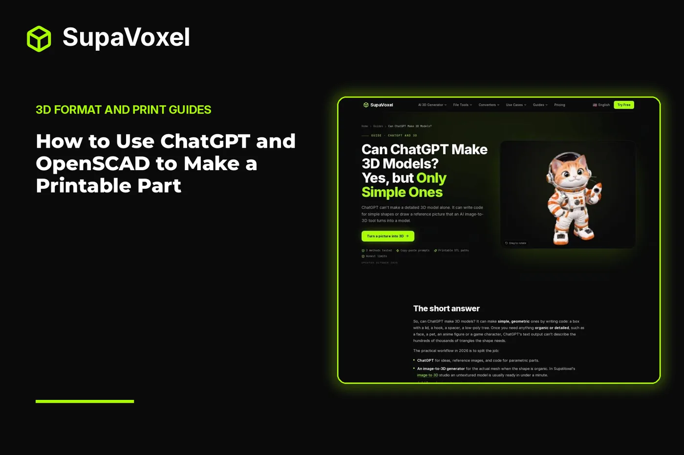
A hook is a reasonable first project because I can describe its overall size, mounting holes and projection from the wall. A face or a pet is not: prose cannot specify all the connected surfaces that make a convincing organic mesh. SupaVoxel’s Can ChatGPT Make 3D Models? guide makes that distinction and lays out the code-based route for simple printable parts.

The guide separates geometric parts that suit code from detailed shapes that do not.
The goal here is not to get ChatGPT to hand over an STL. I want it to write a short, editable description of a solid. OpenSCAD turns that description into geometry and exports the file. Keeping those jobs separate makes mistakes easier to find: I can read the dimensions in the script, see the shape in the preview and inspect the final export.
Before prompting, sketch the hook on paper. Mark what each dimension controls. “Wide” might mean the mounting plate, while “deep” means how far the hook projects from the wall. If I leave those meanings open, the script can run perfectly and still make the wrong part.
Step 1: Ask for a variable-driven script
I start with a prompt that names the software, the units and the features. For this example, the dimensions are:
- Mounting plate — 40 mm wide and 60 mm tall.
- Plate thickness — 5 mm.
- Hook projection — 25 mm from the plate.
- Mounting holes — two 4 mm countersunk holes, 30 mm apart.
My prompt would be:
Write an OpenSCAD script for a wall hook with a 40 mm wide, 60 mm tall mounting plate that is 5 mm thick. Add a curved hook at the bottom that projects 25 mm from the plate. Add two 4 mm countersunk mounting holes with centers 30 mm apart. Use millimeters, put editable variables for the dimensions at the top, and comment each block. Make the hook and plate overlap so they form a connected solid. Explain any dimensions I still need to choose.
That last sentence matters. The prompt does not specify a screw-head size or fully define the hook’s curve. I would rather see those decisions identified than mistake ChatGPT’s guesses for my design requirements. Before printing, I need to check the countersinks against the screws I intend to use and decide whether the hook’s shape gives the object it will hold enough clearance.
Variables also make iteration less fragile. If the plate needs to be thicker, I can change its thickness variable rather than ask for an entirely new script. A fresh answer might quietly alter the hole spacing or move the hook.
Step 2: Preview, then correct one problem at a time
I paste the script into OpenSCAD and press F5 for a preview. At this stage, I am looking for the broad shape, not trying to approve the print. Is the hook at the bottom? Do the holes pass through the mounting plate? Is the projecting part attached rather than floating beside it?
If OpenSCAD reports an error, I copy the exact message back into ChatGPT and ask it to fix only that error. If the script runs but the shape is wrong, I describe the visible problem instead: “The hole cuts are outside the plate,” or “The hook does not intersect the mounting plate.” Small, specific corrections are easier to verify than a request to redesign everything at once.
I also read the variables and the operations around the holes. In OpenSCAD, a cut only removes material where the cutting shape intersects the solid. Code can therefore be syntactically valid while a misplaced hole does nothing. Likewise, parts intended to form one object need to meet. The preview is where I catch those basic relationships before committing to a render.
Step 3: Check the design as a physical part
A closed model is not automatically a useful print. I check the mounting faces, hole locations and the path by which the hook connects to the plate. The printed hook must carry its load through that connection; a narrow neck or an abrupt transition deserves a closer look even if the model slices.
I also check thin features in the slicer. As a warning sign, walls under about 0.8 mm can disappear with a 0.4 mm nozzle. The script’s stated plate thickness does not guarantee that every edge or curved portion is equally substantial. I inspect the sliced layers rather than relying on the overall dimensions alone.
This is where I separate geometry from fit. ChatGPT can place holes at the requested spacing, but it cannot know where the holes in my wall fixture actually are unless I measure and provide that information. I would verify the real mounting hardware, the screw heads and the object the hook is meant to hold before treating the model as finished.
Step 4: Render, export and inspect the STL
Once the preview matches the sketch, I press F6 to render the model. Then I use File → Export → STL. Rendering before export is an important distinction: the quick preview helps me edit, while the render resolves the geometry I am sending onward.
I open the exported STL in a viewer and rotate it. I check that the holes are present, the hook and plate form the intended shape, and nothing unexpected sits away from the main part. Then I import it into my slicer and check its physical size and layer preview.
STL does not store units. A slicer may interpret the coordinates as millimeters, but the file itself cannot confirm that choice. That is why I put millimeters in the original prompt and still check the imported size. If it is wrong, I return to the script or import settings rather than scaling blindly until it looks plausible.
Choose the file you share
For this OpenSCAD workflow, STL is a practical export to inspect and slice. It carries the shape, but not the units, colors or print settings. If I want to preserve a slicer setup alongside the model, I save the slicer project as 3MF. SupaVoxel’s best file format for 3D printing guide explains why 3MF is a strong default for sharing print projects, while STL remains a widely accepted fallback.
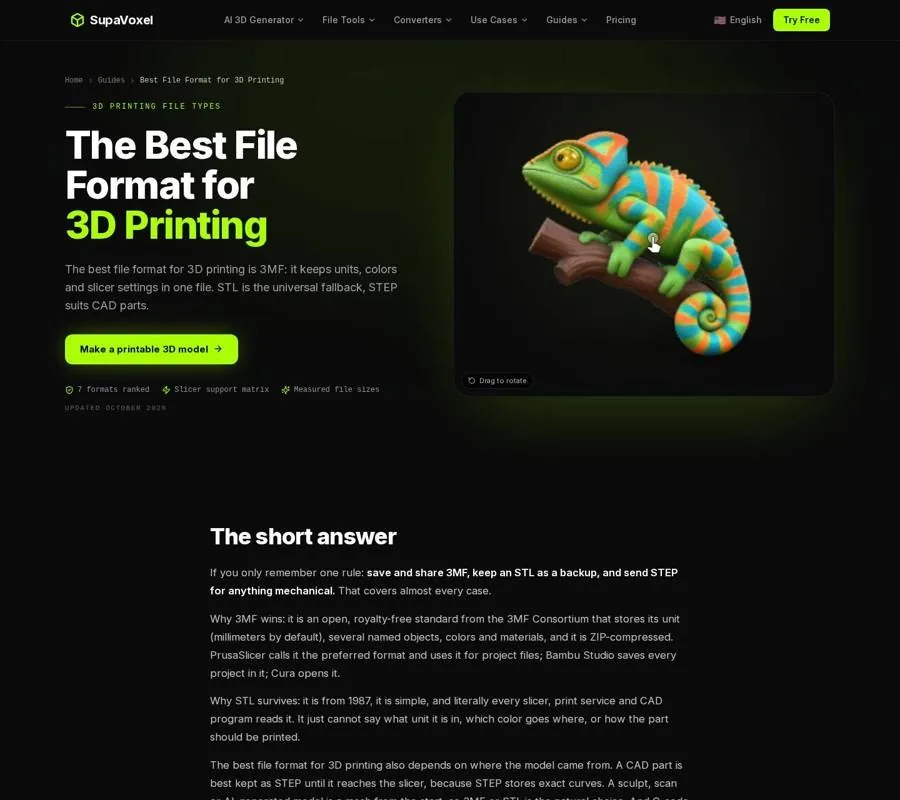
The format guide compares what a model file and a slicer project can retain.
I keep the OpenSCAD source as well. An STL is a mesh of triangles, not a convenient record of the named dimensions in my script. If I need to move the mounting holes later, editing the source and exporting again is clearer than trying to reshape the mesh.
Know when to change methods
Code is a good fit when I can define the part with dimensions and simple solids. It is a poor fit when the source is a picture whose details I want to preserve. A clean logo might need an extrusion; a photograph intended for backlighting needs a lithophane; a sculpted surface calls for a relief. SupaVoxel’s 2D to 3D guide helps choose among those results before turning an image into a printable file.
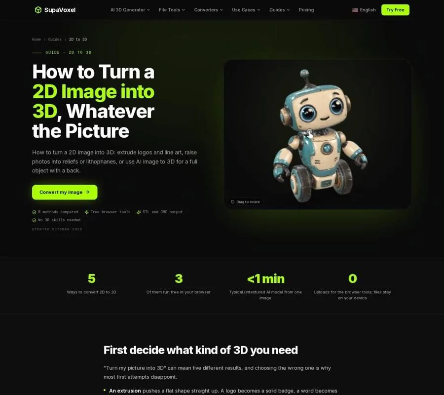
The image-to-3D guide distinguishes extrusions, reliefs, lithophanes and full models.
For the wall hook, I would stay with OpenSCAD. Its value is not that ChatGPT can imagine any shape I describe; it is that I can name the important dimensions, inspect how the script uses them and revise the part without starting over.
FAQ
Can ChatGPT create the STL directly?
It may try to make a basic file, but asking for OpenSCAD code and exporting the STL yourself gives you an editable source and a chance to inspect the geometry first.
Why does my OpenSCAD script preview but fail to make the intended cut?
The cutting shape may not intersect the solid where you expect. Check its position and dimensions, then describe that specific problem when asking ChatGPT for a correction.
Is a rendered STL ready to print?
Not necessarily. Confirm its imported size, look for missing or disconnected features, and inspect thin areas in the slicer’s layer preview before printing.
Want to try it yourself?
Try Supavoxel →